XT-CF-Lite V4: Difference between revisions
Numberformat (talk | contribs) |
Numberformat (talk | contribs) |
||
| Line 11: | Line 11: | ||
== Quality Check == | == Quality Check == | ||
Depending on your skill level, soldering on the connector is the most challenging part of the build. It should be the first thing you solder and test. | |||
You will need a multi-meter with an audible connectivity test function. If the test fails you can use a solder wick to fix the bridges or if that doesn't work then a hot air gun | Testing the solder connections on the CF-50 connector is tedious but critical at this point. A bad solder joint can at best cause your card not to work and at worst fry your computer. | ||
You will need a multi-meter with an audible connectivity test function. If the test fails you can use a solder wick to fix the bridges or if that doesn't work then use a hot air gun to de-solder and start over. Just don't get 2nd burns while doing it. Don't ask! | |||
If all else fails I have standalone PCBs and CF-50 connectors for very low cost [https://www.ebay.com/usr/numberf55 in my eBay store] if you are just looking to start fresh. | |||
=== Procedure === | === Procedure === | ||
Revision as of 00:38, 8 October 2021
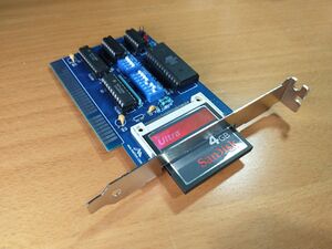
This is a place holder page for the XT-CF-Lite V4 card.

Tips
- This board has a CF card adapter component which requires SMD soldering. Solder this on first. Its important to not use expired solder paste. If its older than 2 months throw it out. Solder paste has flux in it and if its old the flux looses its capability resulting in solder bridging.
- Make absolutely sure that there is no solder bridging on the CF card adapter. Check with a multi-meter for shorts.
- 4GB card is the maximum recommended card for this adapter. It offers the maximum space allowed on the FAT16 (2GB) and IDE standard (2 Drives) however DOS takes a long time calculating the available space. You can still purchase the 4GB card and partition it in Linux to a smaller value depending on the actual space you need.
Quality Check
Depending on your skill level, soldering on the connector is the most challenging part of the build. It should be the first thing you solder and test.
Testing the solder connections on the CF-50 connector is tedious but critical at this point. A bad solder joint can at best cause your card not to work and at worst fry your computer.
You will need a multi-meter with an audible connectivity test function. If the test fails you can use a solder wick to fix the bridges or if that doesn't work then use a hot air gun to de-solder and start over. Just don't get 2nd burns while doing it. Don't ask!
If all else fails I have standalone PCBs and CF-50 connectors for very low cost in my eBay store if you are just looking to start fresh.
Procedure
- Check for short across the C8 capacitor.
- Test connectivity starting from pin 1 working your way up to 50. Some pins are not connected (NC) so you can skip over those example 24-31. Very gently touch the pin of the connector with one end of the probe and the other probe to the numbered point on the board. Point 34, 35 are VIAs and not pins.
- Next we test the letters. There should be NO connectivity between the points listed with letters. If there is connectivity then there is a solder bridge on the 2 pins that share the letter.
Use the following image to quality check the soldering job. Click on the image then next page click again to enlarge.
Address settings
My personal experience its best to initially setup your card with the following DIP Switch settings. If you choose to use this with a floppy controller it will allow you to have the floppy controller at ROM address 0x8000 which is lower than this controller's address. If you are using the Xi8088 Processor board then make sure SW2.2 is OFF otherwise it will conflict with this card.
IO Base Address: 0x300 this means SW1.1-4 All ON
SW2.1-2 = 11
ROM Address: 0xCA000 SW2.3-7: 11010
Check the back of the card for different address settings if the above doesn't suit you needs.
Boot up

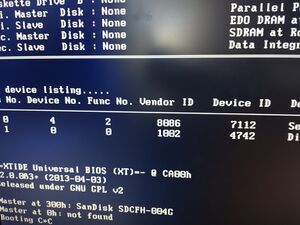
During the bootup if your card doesn't have any conflicts then you will see the XT-IDE menu. This will allow you to enter commands to control how your system boots.
Type: "A A" to boot from the A drive. This will be required if you want to install DOS for the first time from the A drive. Once DOS is installed you *MAY* need to again boot from the A: drive and issue the fdisk /mbr command to install the MBR to the C drive as the DOS 6.22 setup does not do this by default.
Post build
- It is recommended to boot the computer and install DOS 6.22. This will format your drive and install the DOS system which has tools you can use to manage your system.
- Once you are booting from the CF card you can run fdisk again to create a extended partition and create a drive D:
- Format drive D in order to use the second half of the 4GB CF card by issuing the "format /s d:" command.
Troubleshooting
- Hard drive does not boot - try fdisk /mbr
- Cannot load COMMAND, system halted - Make sure that there is a line in AUTOEXEC.BAT that reads "COMSPEC=X:\PATH" where "X:\PATH" is wherever COMMAND.COM resides. Edit the PATH command in your AUTOEXEC.BAT file, if you are trying to run a command in another directory that should be accessible from anywhere.
- System gets very unstable and/or the data on the Compact Flash drive gets corrupted. There may be many reasons for this. During my testing I noticed that the card is very prone to noise on the bus. Please ensure that card is located as close as possible to the processor board. Other reason is that the Compact Flash card may not be fully compatible with the board. Replace the CF card with another one and try again.