XT-CF-Lite V4
Introduction
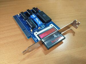
This is a compact flash card adapter that allows you to emulate a standard hard drive using a compact flash memory card. Here is a YouTube Video by Necroware: [https://www.youtube.com/watch?v=pCdQ6MWnNpU] describing XTIDE which this product is based on.
How to Purchase
This kit is available on my eBay store https://www.ebay.com/usr/numberf55/ or for an additional discount contact me at support@noami.us or 1 347 604 2083 with your name and order details I will provide a total and instructions for payment by check. Once it clears the item will be sent out.

Assembly Tips
- This board has a CF card adapter component which requires SMD soldering. Solder this on first. Its important to not use expired solder paste. If its older than 2 months throw it out. Solder paste has flux in it and if its old the flux looses its capability resulting in solder bridging.
- Make absolutely sure that there is no solder bridging on the CF card adapter. Check with a multi-meter for shorts.
- 4GB card is the maximum recommended card for this adapter. It offers the maximum space allowed on the FAT16 (2GB) and IDE standard (2 Drives) however DOS takes a long time calculating the available space. You can still purchase the 4GB card and partition it in Linux to a smaller value depending on the actual space you need.
- Resistor R5 is not required. Actually it will prevent the card from working if its installed. Therefore its is not included in the kit.
Post Assembly & Cleaning
Once you have your board assembled you will need to clean the flux off the board. Depending on the flux you used some flux can remain conductive and result in computer glitches.
I have found the following procedure to be very effective in cleaning the board of any type of solder flux.
- Some flux are water soluble so just rinse the back side in the sink with some soapy water and an old tooth brush. Try not to get water on the front side. Little water is okay.
- If that doesn't work then Spray WD40 on the back of the board (not kidding). Then use dish washing detergent with the brush to remove the WD40.
- Perform the final rinse.
- Use a hair dryer to to dry the board and let it sit for few hours before proceeding to the next steps.
Firmware
Download the 8kb firmware by clicking here. If you purchased the kit from my eBay store its already burned onto the chip. If you purchased the kit prior to March 2022 you may want to update to the newest version. It offers a bit more performance compared to the original from 2013.
Quality Check
Testing the solder connections on the CF-50 connector is tedious but critical at this point. A bad solder joint can at best cause your card not to work and at worst fry your computer.
You will need a multi-meter with an audible connectivity test function. If the test fails you can use a solder wick to fix the bridges or if that doesn't work then use a hot air gun to de-solder and start over. Just don't get 2nd degree burns while doing it. Don't ask!
If all else fails I have standalone PCBs and CF-50 connectors for very low cost in my eBay store if you are just looking to start fresh.
Quality Check Procedure
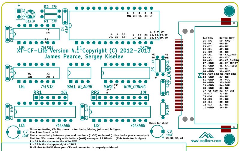
- Check for short across the C8 capacitor.
- Test the letters. There should be NO connectivity between the points listed with letters. If there is connectivity then there is a solder bridge on the 2 pins that share the letter. Use a solder wick to fix this situation.
- Next we test connectivity starting from pin 1 working your way up to 50. Some pins are not connected (NC) so you can skip over those example 24-31. Very gently touch the pin of the connector with one end of the probe and the other probe to the numbered point on the board. Point 34, 35 are VIAs and not pins. They may be painted over so look out for that.
Use the following image to quality check the soldering job. Click on the image then next page click again to enlarge.
DIP Switch Settings
Make sure to disable IDE controllers in your motherboard BIOS if using this card with motherboards with built in IDE controller.
SW1 - I/O Address Selection
 SW1.1	 SW1.2	 SW1.3	 I/O Address
 ON	 ON	 ON	 0x300
 ON	 ON	 OFF	 0x320
 ON	 OFF	 ON	 0x340
 ON	 OFF	 OFF	 0x360
 OFF	 ON	 ON	 0x380
 OFF	 ON	 OFF	 0x3A0
 OFF	 OFF	 ON	 0x3C0
 OFF	 OFF	 OFF	 0x3E0

SW1.4 - Not Used
SW2.1 - EEPROM Enable
 OFF	 EEPROM disabled
 ON	 EEPROM enabled
SW2.2 - EEPROM Write Enable
 OFF	 EEPROM write disabled
 ON	 EEPROM write enabled
SW2.3 - SW2.7 - EEPROM Address Selection
 SW2.3	 SW2.4	 SW2.5	 SW2.6	 SW2.7	 EEPROM Address
 ON	 ON	 ON	 ON	 ON	 0xC0000
 ON	 ON	 ON	 ON	 OFF	 0xC2000
 ON	 ON	 ON	 OFF	 ON	 0xC4000
 ON	 ON	 ON	 OFF	 OFF	 0xC6000
 ON	 ON	 OFF	 ON	 ON	 0xC8000
 ON	 ON	 OFF	 ON	 OFF	 0xCA000
 ON	 ON	 OFF	 OFF	 ON	 0xCC000
 ON	 ON	 OFF	 OFF	 OFF	 0xCE000
 ON	 OFF	 ON	 ON	 ON	 0xD0000
 ON	 OFF	 ON	 ON	 OFF	 0xD2000
 ON	 OFF	 ON	 OFF	 ON	 0xD4000
 ON	 OFF	 ON	 OFF	 OFF	 0xD6000
 ON	 OFF	 OFF	 ON	 ON	 0xD8000
 ON	 OFF	 OFF	 ON	 OFF	 0xDA000
 ON	 OFF	 OFF	 OFF	 ON	 0xDC000
 ON	 OFF	 OFF	 OFF	 OFF	 0xDE000
 OFF	 ON	 ON	 ON	 ON	 0xE0000
 OFF	 ON	 ON	 ON	 OFF	 0xE2000
 OFF	 ON	 ON	 OFF	 ON	 0xE4000
 OFF	 ON	 ON	 OFF	 OFF	 0xE6000
 OFF	 ON	 OFF	 ON	 ON	 0xE8000
 OFF	 ON	 OFF	 ON	 OFF	 0xEA000
 OFF	 ON	 OFF	 OFF	 ON	 0xEC000
 OFF	 ON	 OFF	 OFF	 OFF	 0xEE000
 OFF	 OFF	 ON	 ON	 ON	 0xF0000
 OFF	 OFF	 ON	 ON	 OFF	 0xF2000
 OFF	 OFF	 ON	 OFF	 ON	 0xF4000
Additional Notes
- Make sure that selected I/O and EEPROM addresses do not conflict with other devices
- Addresses 0xC0000 - 0xC6000 will conflict with EGA/VGA BIOS extension
- Addresses 0xC8000 - 0xCA000 might conflict with XT Hard Disk BIOS extension
- Addresses 0xE0000 and up might conflict with system BIOS on newer motherboards
- It is recommended to disable EEPROM write once XT IDE BIOS extension is programmed and configured
Boot Screen
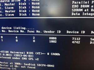
Boot Screen should look like this: -=XTIDE Universal BIOS (XT)=- @ Cxxxh If not seen on boot, then there is an address conflict or an issue with the BIOS Extension EEPROM
Address settings
My personal experience its best to initially setup your card with the following DIP Switch settings.
Try putting the XT-IDE Extension ROM on Address 0xCA000 SW2.3-7(11010) and if you have the floppy controller put it on 0xC8000 SW2.3-7 (11011)
If you are using the Xi8088 Processor board then make sure SW2.2 on the xi8088 is OFF otherwise it will conflict with this card. Based on my testing address conflicts will most likely erase the EEPROM so before plugging it in make sure there are no conflicts. If your EEPROM got erased then download the firmware bin file and use a programmer to re-program.
IO Base Address: 0x300 this means SW1.1-4 All ON
SW2.1-2 = 11
Check the back of the card for different address settings if the above doesn't suit you needs.
Boot up

During the bootup if your card doesn't have any conflicts then you will see the XT-IDE menu. This will allow you to enter commands to control how your system boots.
Type: "A A" to boot from the A drive. This will be required if you want to install DOS for the first time from the A drive. Once DOS is installed you *MAY* need to again boot from the A: drive and issue the fdisk /mbr command to install the MBR to the C drive as the DOS 6.22 setup does not do this by default.
Post build
- It is recommended to boot the computer and install DOS 6.22. This will format your drive and install the DOS system which has tools you can use to manage your system. Dont forget to reboot with the same MSDOS install floppy Press F3 twice and type fdisk /mbr to install the MBR on your hard drive. Otherwise your system will display "Booting C>>C" and hang.
- Once you are booting from the CF card you can run fdisk again to create a extended partition and create a drive D:
- Format drive D in order to use the second half of the 4GB CF card by issuing the "format /s d:" command.
Partitioning and Formatting a 4GB CF card
This section describes how to use the maximum space on the 4GB Compact Flash Card. This assumes you just completed the DOS 6.22 initial installer program. The default installer will create the primary partition and format it using the maximum space that DOS can address which is 2GB. In order to use the rest of the card you would need to manually create an extended partition using the remaining space allocate a drive letter d: and format it. Once complete you will have a drive C: and D: both with 2 GB allocated space each.
- Using fdisk select "Create DOS partition or Logical DOS Drive" then "Create Extended DOS Partition". Use the remaining space
- When it's done it will ask you to create a logical drive on the extended partition. Just follow the remaining steps
- Exit fdisk it will ask you to reboot your system.
- Once your system boots you will need to format drive D:. To do this type "format d:" It will ask you to confirm and then ask for the volume label. I typically name the second drive "DATA" but you can choose whatever you want.
- Once format is complete your drive is ready to use.
If you are having trouble I do offer compact flash cards with FreeDOS 1.3 pre-installed and ready to boot at my eBay store. If you have a spare Linux machine and prefer to do it yourself you can follow instructions available here: https://wiki.noami.us/index.php/FreeDOS_1.3_Installation.
Troubleshooting
- XT-IDE does not start and you don't see the XTIDE boot screen.
- Make sure you did not solder in R5. This resistor is not required and will actually prevent the card from working properly if you have installed it on the board.
- XT-IDE does not start and you don't see -=XTIDE Universal BIOS (XT)=- @ Cxxxh at the boot screen.
- This means that either there is an address conflict (More likely) or your BIOS extension ROM is not at a high enough address. Check to make sure that your XTIDE ROM extension is at a higher address compared to floppy controller. C8000 is good address for a floppy extension rom and and CA000 for the XTIDE BIOS Extension ROM.
- It is also possible that your EEPROM has been electronically erased. Due to address conflict they sometimes become erased in this case please use an EEPROM programmer and re-flash the firmware by downloading it from this page or send the chip back for reprogramming.
- System displays "Booting C>>C" and hangs.
- Boot from drive A using an MSDOS floppy that contains fisk. Press A on the XTIDE prompt and at the DOS prompt type "fdisk /mbr". This will install a Master Boot Record on your new hard drive. I have installed DOS 6.22 many times and it does not install an MBR on your primary disk you have to do this step manually.
- If still having trouble consider purchasing a CF card from my store. It comes with FreeDOS 1.3 pre-installed and ready to boot.
- Cannot load COMMAND, system halted
- Make sure that there is a line in AUTOEXEC.BAT that reads "COMSPEC=X:\PATH" where "X:\PATH" is wherever COMMAND.COM resides. Edit the PATH command in your AUTOEXEC.BAT file, if you are trying to run a command in another directory that should be accessible from anywhere.
- System gets very unstable and/or the data on the Compact Flash drive gets corrupted.
- There may be many reasons for this. During my testing I noticed that the card is very prone to noise on the bus.
- Please ensure that card is located as close as possible to the processor board.
- The Compact Flash card may not be fully compatible with the board. Replace the CF card with another one that works in 8-bit mode. Not all of them do.
- My second XT-CF card is not detected.
- Currently 2 XT-CF cards on a single machine are not supported.
