ISA Backplane
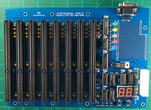
MicroATX ISA Backplane - Version 1.1
This backplane supports bus width up to 16 bits. It has onboard POST code indicators as well as a -5V regulator allowing you to use it with modern power supplies.

Available For Sale
- Bare PCB
- Individual Components
- Full Component Kit
Features
- ATX Power Connector
- 16 Bit ISA bus
Required Tools
- Soldering Iron,
- Flux
- Rosin core solder
- Voltmeter
Assembly Steps
Start with the shorter components first. This way you can lay the board down flat on the table and be able to solder them in. The taller components go next. The recommended order is as follows.
1. IC Sockets
| component type | reference | Name | Qty |
|---|---|---|---|
| socket | U5, U6, U7 | 14 pin 300 mil DIP socket | 3 |
| socket | U1, U2 | 16 pin 300 mil DIP socket | 2 |
| socket | U3, U4 | 20 pin 300 mil DIP socket | 2 |
2. Capacitors
| component type | reference | Name | Qty |
|---|---|---|---|
| PCB | PCB | 1 | |
| Capacitor | C1 - C51 | 10 uF ceramic, 5.08 mm lead spacing | 51 |
| Capacitor | C52 | 1 uF ceramic, 5.08 mm lead spacing | 1 |
| Capacitor | C53 - C59 | 0.1 uF ceramic, 5.08 mm lead spacing | 7 |
Polarity doesn't matter unless you are using electrolytic ones.
3. ISA Slots
| component type | reference | Name | Qty |
|---|---|---|---|
| Connector | BUS1 - BUS8 | Edge Connector 98 Pin | 8 |
4 LED Lights
| component type | reference | Name | Qty |
|---|---|---|---|
| Diode | D1 - D5 | 5 mm LED | 5 |
5 ATX Power connector
| component type | reference | Name | Qty |
|---|---|---|---|
| Connector | P3 | ATX Connector | 1 |
LED Display Configuration
7-Segment Decoders and Matching Displays
The ISA Backplane board supports a variety of 7-segment decoders and common anode / common cathode type LED displays. Please use the following table to determine the proper configuration.
POST Codes and what they mean
[Reference information available here]
Power On and Test
The goal is to identify any short circuits that would cause problems. Before powering on the device check to see if there are shorts across any of the rails of the PCB.
- Turn on the backplane and use a volt meter to check voltage across the PCB including the expansion slots.
- Plug in the ATX power connector and the PCB and the standby light should go on.
- Then click the power button and the power lights should go on.
- The -5V regulator is option and if your power supply does not provide -5V then you can solder that in as well. Once the regulator is installed the -5V light should go on as well.