Difference between revisions of "Xi8088 Version 2.0"
Numberformat (talk | contribs) |
Numberformat (talk | contribs) |
||
| Line 3: | Line 3: | ||
Xi 8088 IBM PC/XT compatible processor board. The information on this page is specific for the integrated circuit kit I sell online. Most information could be used at your own risk if you are sourcing your own chips. | Xi 8088 IBM PC/XT compatible processor board. The information on this page is specific for the integrated circuit kit I sell online. Most information could be used at your own risk if you are sourcing your own chips. | ||
| − | == | + | == This Page Updates Often == |
| − | If | + | If you have received this page as a printout then please note that there may have been changes to the instructions below. In order to receive the most up to date information please visit [wiki.noami.us] |
== Features == | == Features == | ||
Revision as of 10:19, 8 November 2021
Introduction
Xi 8088 IBM PC/XT compatible processor board. The information on this page is specific for the integrated circuit kit I sell online. Most information could be used at your own risk if you are sourcing your own chips.
This Page Updates Often
If you have received this page as a printout then please note that there may have been changes to the instructions below. In order to receive the most up to date information please visit [wiki.noami.us]
Features
- ISA board form factor
- Support of PS/2 keyboard and mouse
- Built-in real time clock with NVRAM
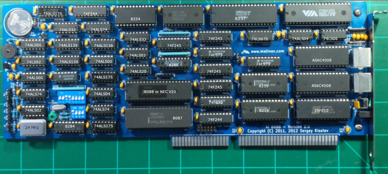
Board Layout
Click on any chip for more information. Most of the chips below lead to blank pages. I am working on populating them with more info but currently its a work in progress.

Board Assembly
Tips:
- Short components first then taller ones.
- Keep in mind to use the 510 ohm resistors in the crystal circuit and NOT the 33pf caps.
- The rest of the components should be placed based on the printed locations on the board.
- The notch on each IC should all be facing the same direction (left)
- The resistor packs have a dot on one side that is pin 1 location.
- One and only one switch in SW3 should be in the on position (Wait state 1 is good starting point)
- Check for shorts often for example: After soldering all the sockets and passive components and before and during the process of inserting the chips into their sockets. There have been times where a shorted chip made it into the mix and it makes finding the bad chip very difficult if you check for shorts after everything is installed. See troubleshooting below for corrective actions.
Post Assembly & Cleaning
Once you have your board assembled you will need to clean the flux off the board. Depending on the flux you used some flux can remain conductive and result in computer glitches.
I have found the following procedure to be very effective in cleaning the board of any type of solder flux.
- Spray WD40 on the back of the board (not kidding).
- Scrub it in both the x and y direction with an old tooth brush.
- Then rinse with water scrubbing it with the toothbrush. Try not to get water on the front side. Little water is okay.
- Then use dish washing detergent with the brush to remove the WD40.
- Perform the final rinse.
- Use a hair dryer to to dry the board and let it sit for 24 hours before proceeding.
Jumper Settings
P3 - Speaker
To enable internal speaker connect a jumper across pins 1-2
J2 - Turbo Switch
Jumper this if you want Turbo Enabled. Also check bios setting to enable Turbo
J3 - IRQ12 Mouse Interrupt Support
Position 1-2 (upper 2 pins) PS/2 mouse interrupt connected to the plug in the back of the card
Position 2-3 Mouse Interrupt connected to the ISA Bus
Memory Map

The 20 bit address bus of the 8088/86 allows 1 Mb of memory space with address range from 00000-FFFFF. During the design phase of the first IBM PC, engineers had to decide the allocation of the 1-megabyte memory space to various sections of the PC. This memory allocation is called a memory map.
| Start Address | End Address | Size | Purpose | Comments | ||||||||||||||
| 0x00000h | 0x9FFFFh | 640 KiB | Base memory | |||||||||||||||
| 0xA0000h | 0xBFFFFh | 128 KiB | Display memory | |||||||||||||||
| 0xC0000h | 0xEFFFFh | 192 KiB | Upper memory blocks (UMB) and BIOS extension ROMs | Consists of six 32 KiB user configurable blocks, can be either mapped to SRAM (to be used as UMB) or used for BIOS extension ROMs
| ||||||||||||||
|---|---|---|---|---|---|---|---|---|---|---|---|---|---|---|---|---|---|---|
| 0xE0000h | 0xEFFFFh | 64 KiB | On-board BIOS extension ROM | This is the upper 64 KiB of the 192 KiB block seen above. System flash ROM can be mapped here, so it can be used for BIOS extensions
| ||||||||||||||
| 0xF0000h | 0xFFFFFh | 64 KiB | System BIOS | Currently BIOS uses only top 32 KiB of this space (0xF8000h - 0xFFFFFh). The other 32 KiB part is mapped to the flash ROM and can be used for BIOS extensions
|
| Position | Description |
| 8 | ON = Monochrome display (MDA)
OFF = Color display (CGA) |
In summary if you have a VGA card in the system and 128Kb EEPROM chip and want to use the maximum amount of available memory then switch SW2.2,3,4 should be ON and the rest in the OFF position.
Burning the BIOS onto 39SF010 128k EEPROM chip
You may use the 128k bios downloaded from the designer's website however this version is a bit old. The latest source is available the following github page: https://github.com/numberformat/8088_bios but it does require compiling using NASM.
Download the Latest BIOS
If you prefer the latest version then see below.
Download the 128k BIOS by File:Bios-xi8088.hex. This file was built using NASM 2.14.02 with the latest checked out version from the designer's GitHub page. You could compile the file yourself by following the instructions outlined on that page.
Burn the bios128k-2.0.hex/bin file starting from the beginning address space of the EEPROM chip.
If you inspected the BIOS binary image you may be wondering why the upper half of the ROM chip's address range is empty. The reason for this is the design of the board internally flips the A16 address line that is going to the ROM chip using an logic inverter (U40 pin 3,4). To the processor the lower half of the ROM's address range (0x00000) appears at the upper half (0x10000).
The position of the SW2.7 does not affect the boot up. The ROM chip will always respond to the 0xFxxxx address range and if you have SW2.7 in the OFF position this chip will also be active for the 0xExxxx address range thus utilizing the now inverted 64Kb bottom address range of the chip for any custom BIOS extension code you decide to put there.
During product testing the inexpensive TL866 II writer was used. These are available on Amazon or eBay.
Boot Up and BIOS Settings

Before plugging in the processor card into your backplane perform a final continuity check. The resistance should be above 4k Ohm. You can test this at the top left and bottom right pins of the math co-processor socket.
Once you turn on your machine it will go thru the POST sequence. Hopefully it does not find any issues. A screen similar to the one on the right will be displayed. Press F1 to enter BIOS Setup. You will need to setup the date and time and the default clock setting (Turbo / Non Turbo). Type h for the help menu and w to write to the CMOS and exit. If you made a mistake and system does not boot you can find the jumper to short and clear the CMOS settings its located close to the battery. If you notice post cod 60, 61 or 62 then boot in non turbo mode. See troubleshooting guide for more information on those codes.
Installing support cards
Video card. Popular choice is the [Trident Video cards].
Controller Cards: To run software on this computer you would need to install a floppy controller. There are many out there on eBay most will work just fine. Due to reliability concerns with mechanical floppy drives many people choose to purchase a [Gotek USB floppy emulator]. This allows you to simulate 100 floppy disk images onto a single thumb drive.
Running Software
Once you have the floppy drive create a DOS boot disk. DOS 6.22 is the last version that has been tested on this machine. Based on our understanding this is the last version that still supports the 8088 processor.
Hard Drive Support
This board works with the XT-CF-Lite V4 card. Please see the page dedicated to this card for more information.
Mouse Support
Please use the [cute mouse] driver. Save it to a directory and just execute ctmouse.exe to load it. Open your favorite program that has mouse support to test. Example: edit.exe in MS-DOS 6.22
PS/2 Mouse
This processor board supports a PS/2 mouse. There is a jumper setting on the board as described on this page to enable support for it.
Serial Mouse
Serial mouse was also tested and it worked fine. Please note you will need a serial mouse and an ISA card that supports serial communication. You can not use any old USB or PS/2 mouse with a USB or PS/2 to serial adapters. The cheap ones sold online only work if the mouse you have explicitly supports the conversion to serial. You can find these Mice still being sold today but they have become rare. I have a large stock of these I will be posting them shortly watch out for them.
Software and Tools
There are many resources online where you can download vintage software. Once such website is [vetusware.com] it has a very large selection of abandoned and vintage software and I encourage support their efforts by opening a premium account with them.
Benchmarking
CheckIt is a popular tool used for performance testing.
Below is the results from a Intel 8088 running at 8 Mhz.

Below is the results from a NEC V20 running at 8 Mhz.

| Name | Description |
| Dazzle | Shareware Screensaver with colorful effects works on EGA/VGA cards. Can be left running overnight for "burn in" testing. |
| 8088 MPH | DEMO works with only a PC Speaker but requires a CGA card. Displays on VGA but some screens don't look right. |
| 8088_Corruption/8088FLEX | Audio Video Demo Requires sound card. I have not tried it but it seems promising. |
Turbo
To toggle the turbo via software just create a turbotog.com by piping the below file to debug.exe
n turbotog.com
a
in al,61
xor al,04
out 61,al
mov ah,02
mov dl,07
int 21
ret

rcx
13
w
q
Troubleshooting
Board layout and schematics are a must have reference. They are available at the designers website. The following section will try to address some of the common troubleshooting topics.
Electrical short detected during continuity test
If you have tested and found a short while assembling the board check for solder bridges. If none found then it is possible one of the chip is shorted. This has happened to me in the past. To find the bad chip just backtrack. Remove each chip in the order it was installed checking continuity after a few chips. Once the chip is found please contact me for a replacement.
Does not boot

There could be many reasons why its not booting. This section will grow as I get more feedback from others.
- But for now I noticed a common issue is burning the boot ROM in the wrong byte offset on the chip. The A16 line is inverted so the top half of the 128kb ROM chip appears in the bottom half of the address space. See my notes about burning the BIOS to the ROM chip above.
- Use 2 510 ohm resistors for the clock instead of the 2 33pF caps. An example of a clean clock signal (see image to the right).
- Other common issues include bad solder on pins.
= System does not run at 8Mhz
The system speed is set via BIOS setting and jumper J2. Make sure both are enabled.
Keyboard Error 60h or 61h
Start the computer in non turbo mode. (BIOS setting, and jumper J2). Boot the machine and then enter turbo mode. I am looking for a long term solution for this. Possible bug fix in BIOS or using faster F series chips for the U19 & 20 locations. More to come on this so check back.
No sound or continuous sound from speaker

To enable internal speaker connect a jumper across pins 1-2 of the speaker header pins. The speaker should sound the "intel inside" jingle when POST booting. If the speaker emits sound continuously then you need to order a "passive" speaker.
Math Co-processor gets hot
The Math co processor gets so hot that it's really uncomfortable to the touch. This is normal.
POST codes (sent to port 80h during POST)
The system writes post codes as soon as the operation is complete.
e_boot		equ	00h		; Boot the OS
e_start		equ	01h		; BIOS POST started
e_cpu_ok	equ	02h		; CPU test passed
e_dmac_ok	equ	03h		; DMAC initialized
e_low_ram_ok	equ	04h		; low RAM test passed
e_int_ok	equ	05h		; interrupt table initialized
e_pit_ok	equ	06h		; PIT (timer) initialized
e_pic_ok	equ	08h		; PIC initialized
e_kbd_ok	equ	10h		; KBD test passed
e_video_bios_ok	equ	11h		; Video BIOS found
e_video_init_ok	equ	12h		; Video BIOS initialized
e_rtc_init_ok	equ	20h		; RTC initialized
e_cpu_detect_ok	equ	21h		; CPU type detected
e_fpu_detect_ok	equ	22h		; FPU type detected
e_serial_ok	equ	24h		; Serial port scan finished
e_parallel_ok	equ	25h		; Parallel port scan finished
e_ram_start	equ	30h		; RAM test start
e_ram_complete	equ	31h		; RAM test completed
e_ram_esc	equ	32h		; RAM test canceled
e_ext_start	equ	40h		; Start BIOS extension ROM scan
e_ext_detect	equ	41h		; BIOS extension ROM found
e_ext_init_ok	equ	42h		; BIOS extension ROM initialized
e_ext_complete	equ	43h		; BIOS extension scan complete
e_cpu_fail	equ	52h		; CPU test failed
e_low_ram_fail	equ	54h		; low RAM test failed
e_kbd_ctrl_fail	equ	60h		; KBD test - unable to flush KBC output buffer
e_kbd_key_fail	equ	61h		; Unable to send command to KBC
e_kbd_timeout	equ	62h		; KBD timeout
e_kbd_int_fail	equ	63h		; KBD test - interface test failed
e_ram_fail	equ	80h		; RAM test failed

;-------------------------------------------------------------------------
; Minor numbers for keyboard errors
e_kbd_tout_fail	equ	01h		; keyboard timeout sending command
e_kbd_resp_fail	equ	02h		; keyboard no response
e_kbd_nack_fail	equ	03h		; acknowledge response was expected
					; but keyboard have sent something else
e_kbd_rsp2_fail	equ	04h		; keyboard no response byte 2 for BAT
e_kbd_nbat_fail	equ	05h		; BAT OK response was expected
					; but keyboard have sent something else
e_kbd_test_fail	equ	06h		; keyboard controller test failed
e_kbd_int_fail	equ	07h		; keyboard interface test failed
If All Else Fails
I offer board repair service. Please search "xi8088 repair" on eBay and you will find it.