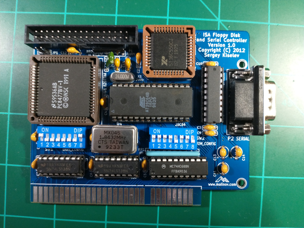
ISA Floppy Disk and Serial Controller
This is a place holder page for the ISA Floppy Disk and Serial Controller
Board Assembly
Install the shorter components first this means installing them in the following order
- 24 Mhz Crystal
- Capacitors, resistor arrays
- DIP Sockets
- DIP Switches
- Square sockets
- Floppy connector
- 9 pin serial header
DIP Switch settings
A good starting point is to set the dip switch 2 and 8 ON. This will put Serial port on IRQ 4. and base address 0x3F8 (COM1).
Note: Only one of SW1.1 - SW1.4 should be ON. All switches can be off if software doesn't use interrupt based I/O. Note: One and only one of SW1.5 - SW1.8 switches should be ON.
For the ROM Address you can switch all of SW3 ON except 5 and 8. This will put the floppy controller ROM at address 0xE8000.
Note: If you are using the XT-CF or similar card then the floppy controller needs to be at a higher address.
See the original designer's website for detailed configuration of the DIP switches.
Troubleshooting
The floppy drive works but the C drive is not detected.
This can happen if you have both the XT-IDE and floppy ROM Extensions installed on the same system where the XT-IDE is at a higher address. You will notice that the usual XT-IDE boot screen will not show. In this case make sure the floppy controller address is higher than the XT-IDE.
For example the floppy controller is at 0xC8000(lower) and the IDE controller is at 0xCA0000 (higher) then swap the addresses by adjusting the DIP switches.
System hangs during boot
The floppy BIOS needs to be configured (Press F2 during boot) see instructions above.
